
This post is my second book review, as introduced in Professional Book Review.
📋 Quick Facts
 Book: Clean Architecture
German translation of Clean Architecture- Author: Robert C. Martin
Translated from English by Maren Feilen and Knut Lorenzen - Target Audience: IT Architects / Software Developers
- My Rating: ⭐⭐⭐⭐⭐ (5/5) - Highly Recommended / Must Read
- Link: Clean Architecture or ISBN: 9783958457249
Quick Verdict: In this book, Robert C. Martin (Uncle Bob) masterfully connects programming paradigms and SOLID design principles to define ‘Clean Architecture’, convincingly demonstrating that these foundational structural rules remain timeless even in the era of Generative AI. Reading this work fundamentally shifts one’s perspective on software engineering by prioritizing application use cases over volatile technologies and runtime mechanics.
💡 My Key Takeaways & Actions
Robert C. Martin, also known as Uncle Bob, has been a software developer since the very beginning and has therefore witnessed all major advancements in software architecture firsthand. He not only describes programming paradigms and software architecture principles but also elucidates their interconnections and reciprocal effects. Following the introduction of design and component principles, he elaborates in detail on the core aspects of software architecture and defines his famous Clean Architecture. It is equally fascinating how Uncle Bob convincingly demonstrates that the foundational rules of software architecture will not drastically change over the coming years — regardless of the rise of Generative AI.
After reading the book, I immediately realized that it had fundamentally shifted my perspective on software architecture — moving away from a heavy focus on technology and runtime systems toward a deep prioritization of application use cases. Furthermore, I am now actively striving to incorporate these foundational principles into my own architectural designs.
My primary takeaways from this book are the following:
- The rules of architecture are always the same.
- The ultimate goal of software architecture or design is long-term efficiency:
The objective of software architecture is to minimize the human resources required to build and maintain the required system.
- Consequently, the fundamental purpose and focus of software architecture is to maximize adaptability.
- Programming Paradigms:
- Structured Programming enabled functional decomposition to reduce system complexity.
- Object-Oriented Programming enabled Inversion of Control, providing the ability to decouple domain logic from infrastructure.
- Functional Programming enabled the isolation of variable manipulations and state changes, allowing the vast majority of system complexity to become stateless and immutable.
- SOLID design principles:
- SRP: The Single-Responsibility Principle
- OCP: The Open-Closed Principle
- LSP: The Liskov Substitution Principle
- ISP: The Interface Segregation Principle
- DIP: The Dependency Inversion Principle
- Component Cohesion Principles and their tension triad:
- Reuse-Release-Equivalence Principle (REP)
- Common-Closure Principle (CCP)
- Common-Reuse Principle (CRP)
- Component Coupling Principles and the Zones of Exclusion:
- Acyclic-Dependencies Principle (ADP)
- Stable-Dependencies Principle (SDP)
- Stable-Abstractions Principle (SAP)
- Architecture must create and maintain architectural options over time:
A good software architect maximizes the number of decisions not yet made.
- Architecture is about drawing lines to create independent components.
- Architectural boundaries manifest across a spectrum of deployment and runtime configurations.
- Implementing full architectural boundaries introduces significant up-front costs and ongoing maintenance overhead.
- Conversely, omitting necessary boundaries can impose even greater long-term maintenance and technical debt costs.
- Architecture level:
A level is defined by the distance from the system inputs and outputs.
- An architecture must scream its purpose: application use cases are first-class citizens, not technology or frameworks.
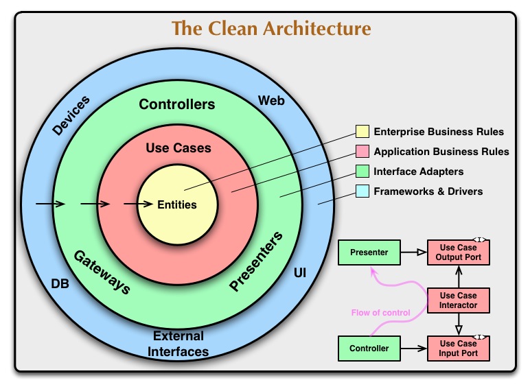
- Clean Architecture overview schematic diagram (image copied from The Clean Architecture):
- Dependency rule:
Source code dependencies must only point inward, toward higher-level policies.
- Services are a runtime detail; note the decoupling trap! Cross-cutting concerns can span across services and are not necessarily in between them!
- In-depth details: database, web, and frameworks.
- Read Chapter 34 — The Missing Chapter over and over.
🔍 The Deep Dive (Summary)
PART I — Introduction
Chapter 1 — What is Design and Architecture?
Software design and software architecture represent identical concepts. The ultimate goal of these disciplines focuses entirely on long-term efficiency.
The objective of software architecture is to minimize the human resources required to build and maintain the required system.
Failing to prioritize maintainability leads to severe technical debt, which increases the total cost of ownership (TCO) and drastically decreases developer velocity. Conversely, engineering productivity increases significantly by implementing workflows like Test-driven development. A common, erroneous mindset dictates launching a product to the market immediately while postponing refactoring and testing to a later phase. This approach fails because the designated time for optimization never materializes. Furthermore, attempts to rebuild an entire system from scratch fail to resolve the underlying issue because market pressure persists throughout the entire rebuilding phase.
Chapter 2 — A Tale of Two Values
Software systems deliver value through two primary dimensions: behavior and structure. The behavior of a system fulfills the specified functional requirements, while a robust structure supports system adaptability, including maintainability and testability. The term “software” itself implies a medium designed to be soft and adaptable. Adaptable systems are inherently superior to systems that merely exhibit correct behavior. Adaptable systems can be fixed and evolved easily, whereas feature-complete but poorly structured systems remain strictly rigid. Consequently, the fundamental purpose and focus of software architecture is to maximize adaptability.
PART II — Starting with the Bricks: Programming Paradigms
Chapter 3 — Paradigm Overview
Programming paradigms limit the capabilities of a programmer by enforcing boundaries on architectural control flow. Each paradigm removes specific freedoms to establish behavioral discipline.
Structured programming imposes disciplined control over direct transfer of control.
By eliminating arbitrary jumps, code organization becomes predictable. Object-oriented development changes how modules interact.
Object-oriented programming imposes disciplined control over indirect transfer of control.
Finally, state management shifts fundamentally in functional systems.
Functional programming imposes disciplined control over variable assignment.
Chapter 4 — Structured Programming
Structured programming restricts the use of unconstrained transfer-of-control statements (such as goto) and replaces them with standardized control flows like sequence, selection (if/then/else), and iteration (do/while). This paradigm aligns with theoretical findings demonstrating that any computable program can be constructed exclusively using sequence, selection, and iteration. Software architectures are inherently composable, built from smaller, modular sub-units. Mathematically, if each sub-module could be proven to operate entirely without error, the aggregate program would itself be error-free. In practice, empirical software testing can only demonstrate the presence of errors, never their complete absence. Despite this limitation, robust and comprehensive testing of individual sub-modules yields a high statistical probability that the overall system will contain minimal defects. Consequently, structured functional decomposition remains a highly effective strategy for managing system complexity.
Chapter 5 — Object-Oriented Programming
Object-oriented programming provides polymorphism in a safe, stable, and highly manageable manner. This technical capability directly enables the implementation of the Inversion of Control (IoC) paradigm, representing a critical architectural value. Through this mechanism, software architects can structure source code dependencies independently, removing the constraint to follow the runtime control flow of the program. For example, this mechanism allows engineering teams to build core domain logic entirely independent of database access layers, successfully separating domain business logic from technical infrastructure concerns.
Chapter 6 — Functional Programming
The functional programming paradigm dictates that variables cannot be explicitly altered after initialization. Eliminating mutable state inherently resolves critical concurrency issues, such as race conditions and resource deadlocks. Adopting functional principles shifts how system state and logic are distributed across an application. Software architects must isolate variable manipulations and state changes into dedicated, explicit modules, designated as mutable components. Conversely, engineering teams should encapsulate the vast majority of domain logic and runtime complexity within stateless, immutable components.
Part III — Design Principles
The primary architectural goals of middle-layer design are to enable modification, ensure easy traceability, and facilitate the reuse of architectural components. The middle layer resides at the module level, positioned directly above the source-code level. The core design principles governing this layer are recognized by the acronym SOLID, though they exhibit slight differences in definitions compared to Wikipedia. These principles include the Single-Responsibility Principle (SRP), which dictates that organizational social structures heavily influence system design to ensure modules have only one reason to change. The Open-Closed Principle (OCP) ensures behavioral modifications occur by adding new code rather than modifying existing code. The Liskov Substitution Principle (LSP) requires interchangeable objects to be mutually substitutable, while the Interface Segregation Principle (ISP) mandates avoiding dependencies on unutilized modules. Finally, the Dependency Inversion Principle (DIP) states that code implementing high-level policies must not depend on code implementing low-level details, meaning details must depend on policies.
Chapter 7 — SRP: The Single-Responsibility Principle
The Single-Responsibility Principle clarifies module boundaries based on organizational stakeholders.
Define a module in this context as being responsible to a single actor.
A common misconception assumes every module must perform only a single task; however, this rule applies strictly to functions and methods, not to modules. The original definition remains paramount, stating that there should be only one reason to change a module. This concept serves as a foundation for future architectural mappings, reappearing in subsequent architectural layers as the Common-Closure Principle (CCP) in Chapter 13 and within the axis-of-change model.
Chapter 8 — OCP: The Open-Closed Principle
The Open-Closed Principle serves as the primary force shaping system boundaries.
A software entity must be open for extension but simultaneously closed to modification.
This principle represents the fundamental motivation driving software architecture. The core methodology requires decomposing the system into distinct components and establishing a suitable dependency hierarchy. This organization ensures higher-level components remain protected from changes in lower-level components, as demonstrated by excellent illustrative examples provided within the book.
Chapter 9 — LSP: The Liskov Substitution Principle
The Liskov Substitution Principle defines structural substitutability through a strict mathematical lens.
The objective is to achieve a substitution property where if, for each object
o1of typeS, there exists an objecto2of typeTsuch that for all programsPdefined in terms ofT, the behavior ofPremains unchanged wheno1is substituted foro2, thenSis a subtype ofT.
While the principle was originally developed to handle inheritance in programming languages, it must be viewed more generally to encompass all types of interfaces and components. The architectural impact of violations is severe; a single violation can have a massive impact on maintainability because numerous exceptions must subsequently be added, maintained, and understood.
Chapter 10 — ISP: The Interface Segregation Principle
The Interface Segregation Principle focuses on interface specialization, requiring teams to design distinct interfaces tailored to specific architectural purposes. Although the concept was originally defined for statically linked programming languages, the principle successfully generalizes to all categories of software components. The general formulation mandates avoiding reliance on modules that provide a broader scope of functionality than required. This concept correlates directly with the Common-Reuse Principle detailed in Chapter 13.
Chapter 11 — DIP: The Dependency Inversion Principle
The Dependency Inversion Principle demands that source code dependencies strictly consist of abstractions, a constraint that is historically challenging to implement. However, it remains entirely feasible to isolate concrete dependencies by utilizing factory components. Operating system components and core platform entities, such as the Java String class, are typically exempted from this architectural rule. Achieving architectural stability requires adhering to strict rules regarding concrete implementation structures: developers must not reference concrete classes, inherit from concrete classes, override concrete methods, or explicitly reference concrete elements by name under any circumstances. To manage dependency creation cleanly, engineering teams should implement the abstract factory pattern, which features a definitive illustrative diagram on page 110. Modern framework mechanisms, such as the Spring (Boot) application context, fully automate this specific instantiation workflow.
PART IV — Component Principles
Chapter 12 — Components
Components represent the smallest deployable units within an architecture, exemplified by formats such as JAR files. A historical review of compilers and linkers demonstrates that modern plug-in architectures — utilizing artifacts like JARs and DLLs — have become the industry standard.
Chapter 13 — Component Cohesion
Component cohesion is governed by three primary principles that dictate how classes should be grouped into larger deployment units. The first is the Reuse-Release-Equivalence Principle (REP):
The granularity of reuse is the granularity of the release.
This means you can only reuse what is in one named component with the same version number and release documentation. The second is the Common-Closure Principle (CCP):
Group classes that are modified for the same reasons and at the same time into the same components. Conversely, separate classes that are modified for different reasons and at different times into different components.
This principle dictates that there should only be one reason to change a module, serving as a direct generalization of the Single-Responsibility Principle (SRP). It is also related to the Open-Closed Principle (OCP), acknowledging that because “closed for modifications” cannot be reached completely, the CCP requires this isolation on a higher component level. The common denominator of this generalization of SRP and OCP is to group all elements that are modified for the same reasons and at the same time, while separating all elements that are modified for different reasons and at different times. The third principle is the Common-Reuse Principle (CRP):
Do not force the users of a component to depend on elements that they do not require.
The CRP instructs engineers to put components together that are usually used together, and to separate classes that are usually not used together. It relates closely to the Interface Segregation Principle (ISP), which requires separating interfaces when methods are usually not used together. The common denominator of ISP and CRP is that systems must not create dependencies on elements that they do not require.
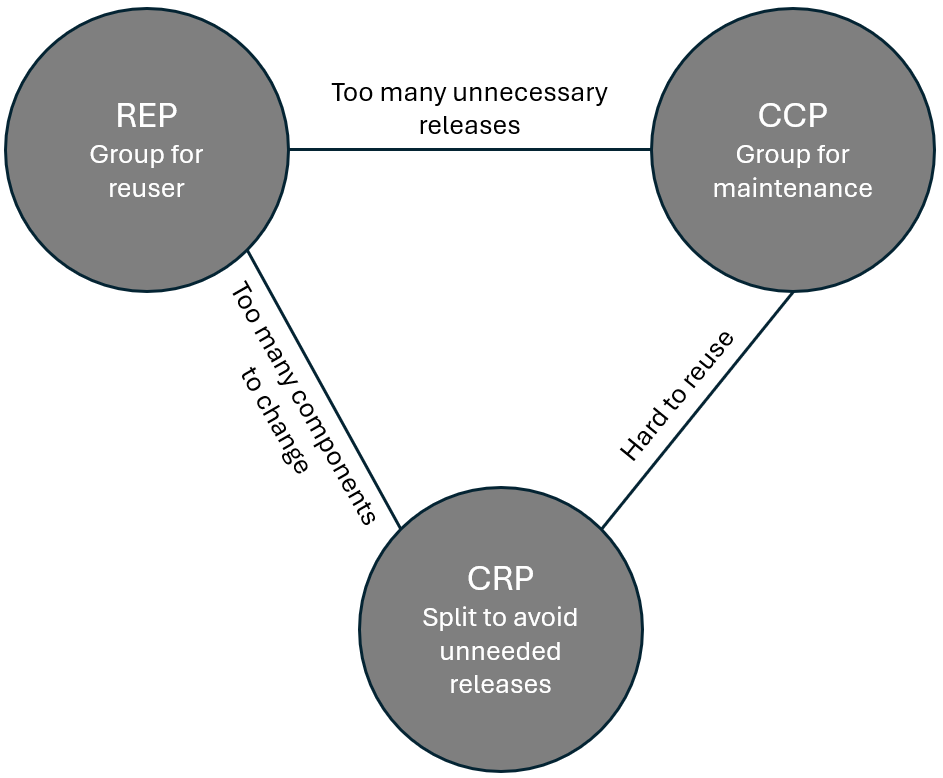 Tension Triad of Component Principles (adapted from page 126)
These three concepts form the Tension Triad of Component Principles depicted above, as they are in constant opposition. REP tends to create big components to reduce their overall number, whereas CRP tends to create small components to reduce unnecessary dependencies. Meanwhile, CCP organizes the components strictly from a maintenance effort point of view. Because of these competing forces, the optimal component definition may change over time and project affordances, as illustrated by the tension diagram on page 126.
Chapter 14 — Component Coupling
Component coupling focuses on managing relationships between deployment units, beginning with the Acyclic-Dependencies Principle (ADP):
Allow no cycles in the component dependency graph.
Violations of the ADP result in complex integration management and difficult impact analyses. Engineering teams can overcome cycles by applying the Dependency Inversion Principle (DIP) or by creating an entirely new component. Because of these structural dynamics, top-down design is not recommended because there is not enough knowledge upfront; instead, component design must be controlled organically by the Single-Responsibility Principle (SRP) and the Common-Closure Principle (CCP). Coupling is further refined by the Stable-Dependencies Principle (SDP):
Dependencies should run in the direction of stability.
Stability of components is defined as the effort required to change the component. It is measured using metrics for instability (I), which rely on Fan-in (the number of incoming dependencies) and Fan-out (the number of outgoing dependencies) to calculate I = Fan-out / (Fan-out + Fan-in). An I value of 0 indicates a component is maximally stable, while an I value of 1 means it is maximally unstable. The SDP states that the I-value of a component should be higher than the I-values of the components it depends upon, though it is important to note that not all components should be stable. This balances with the Stable-Abstractions Principle (SAP):
A component should be as abstract as it is stable.
Common components should be stable but also accessible by many components; therefore, they should be abstract. The SAP states that the stability of a component should relate directly to its abstraction. When combined, the SAP and SDP represent a component-level equivalent of the Dependency Inversion Principle (DIP). The degree of abstraction (A) of components is measured using the number of classes in a component (N_c) and the number of abstract classes and interfaces in a component (N_a), formulated as A = N_a / N_c. Here, A = 0 means no abstract classes exist, and A = 1 means all classes are abstract.
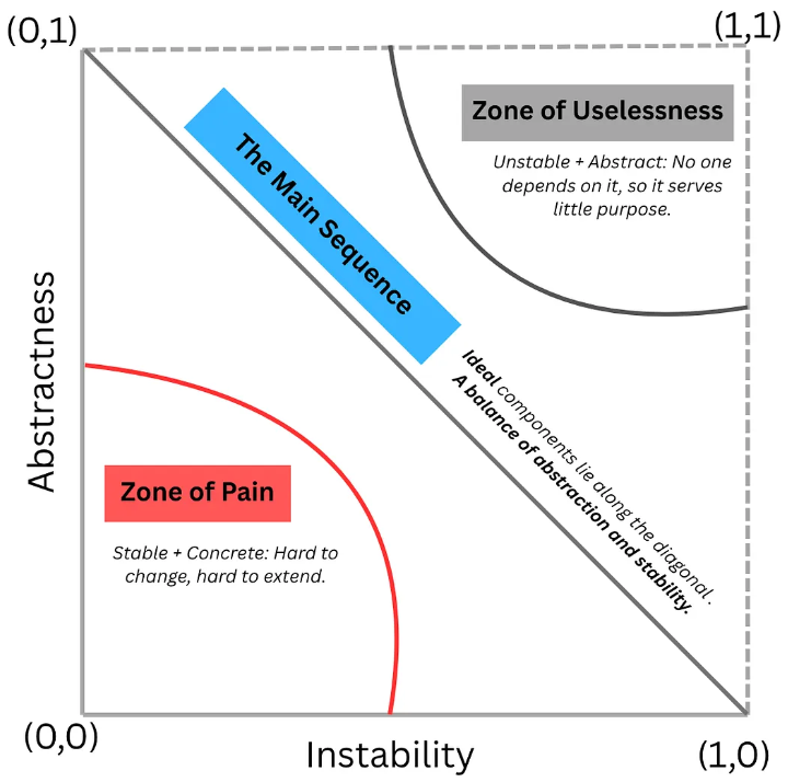 Zones of Exclusion depicted on page 145 (image copied from Breaking Down ‘Clean Architecture’ by Uncle Bob — Part III by Divya Saravanan)
The relationship between these metrics is plotted on the I/A graph, which features zones of exclusion on page 145. The Zone of Pain represents components that are highly stable (many dependent components) and highly concrete (hard to change), with database schemas and the Java String class serving as prime examples. The Zone of Uselessness represents highly abstract classes that are not referenced by any other components. The Main Sequence represents the optimal balance between stability and abstraction. The distance D from the Main Sequence is calculated as D = |A + I - 1|. This specific metric enables valuable statistical analysis, such as examining the normal distribution to analyze components where D is greater than the standard deviation, or monitoring the value of D for a specific component over time.
Part V — Architecture
Chapter 15 — What is Architecture?
Software architecture provides a definitive form or structure for software systems, which is fundamentally shaped by its components and their interactions. While system behavior is determined by functional requirements to fulfill the primary objective of supporting required use cases, the ultimate goal of architecture is to minimize lifetime costs across development, deployment, operations, and maintenance. To achieve this efficiency, the system must create and maintain architectural options over time.
A good software architect maximizes the number of decisions not yet made.
This requires a strict separation of high-level policies, which represent the core business logic, from volatile details. Concrete examples of these details include databases, web frameworks, and device-specific implementations.
Chapter 16 — Independence
Architectural independence allows engineering teams to defer decisions regarding operations as long as possible. If the underlying component structure is robust, the concrete deployment and operational modes can be determined at a later stage without rewriting core logic. Component design must also consider team organization by accounting for Conway’s law:
[O]rganizations which design systems (in the broad sense used here) are constrained to produce designs which are copies of the communication structures of these organizations.
To manage this, architects must implement architectural decoupling across multiple dimensions. First, decoupling horizontal layers requires adherence to the Single-Responsibility Principle (SRP) and the Common-Closure Principle (CCP) to separate implementation details, such as the UI and database access, from core business rules. Second, decoupling vertical use cases separates independent operations, meaning that creating an order is handled distinctly from deleting an order. This combined separation enables completely independent development and deployment cycles. When evaluating code reuse, architects must carefully differentiate between real duplication and accidental duplication. Real duplication should be eliminated systematically, whereas teams must resist the urge to eliminate accidental duplication. For example, similar-looking display outputs have a high probability of diverging in the future if they do not represent the same core concept. Ultimately, decoupling can occur at the source code, deployment, or service level, and architects should defer the selection of the specific level as long as possible because the most suitable decoupling level for a system may change over time.
Chapter 17 — Boundaries: Drawing Lines
The process of drawing physical boundary lines protects important components, such as business rules and policies, from volatile implementation details. Software teams should imagine these boundary lines as a plugin system where different GUIs or databases can be plugged into the system at will, provided the core business cases remain fully protected against these details. In practice, establishing these boundary lines represents a concrete application of the Dependency Inversion Principle (DIP) and the Stable Abstractions Principle (SAP).
Chapter 18 — Boundary Anatomy
Architectural boundaries manifest across a spectrum of deployment and runtime configurations, contrasting monolithic architectures with multi-deployment unit setups. These configurations represent different methodology variations used to enforce component paradigms. In a deployment monolith or modulith, a single deployment unit contains all logical components, meaning component paradigms remain highly valuable for isolation, testing, and structural simplicity. Conversely, full deployments isolate each individual component as a separate deployment unit. Within these setups, runtime execution boundaries operate within a single physical runtime environment. Threads represent distinct runtime execution paths operating within the exact same process space, featuring highly efficient data exchange via shared memory access. Local processes occur when multiple component instances run on the same physical machine but inside isolated operating system processes. This process communication relies on slower mechanisms via standard inter-process communication (IPC), though each individual process can internally spawn and employ multiple threads if required. Finally, service boundaries establish architectural boundaries across distributed services where multiple components or instances are instantiated as independent services. Service communication occurs via standard network protocols, which introduces latency and is relatively slow. However, services offer the flexibility to be deployed across completely different physical or virtual machines, and each individual service can internally utilize local processes or threads if desired.
Chapter 19 — Policies and Level
Policies represent high-level business logic within the application core. The organization of these policies requires defining the precise metric for an architectural “level” within a system.
A level is defined by the distance from the system inputs and outputs.
Components sharing the exact same relative distance from inputs or outputs should be grouped together on the same architectural level. To illustrate this structure, the architectural case study spanning pages 196–198 explicitly applies the Single-Responsibility Principle (SRP), Open-Closed Principle (OCP), Common-Closure Principle (CCP), Dependency Inversion Principle (DIP), Stable-Dependencies Principle (SDP), and Stable-Abstractions Principle (SAP).
Chapter 20 — Business Rules
Business rules are divided into core domains and application mechanics, beginning with critical business rules. These represent policies or procedures that directly result in earning or saving business capital, and they would be applied even if no computer systems were used. Executing these rules relies on critical business data, which refers to the data required to calculate or execute the critical business rules. An entity is an object within a computer system that represents a small portion of these critical business rules. Developers should create a dedicated class for this and separate it completely from all other aspects of the system. In contrast, application use cases are not as puristic as critical business rules and represent application-specific business rules instead. These are required to be handled specifically within an automated system; for example, the contact data of a customer must be created before a user can place an order. Use cases orchestrate entities, but entities are not aware of the use cases. Use cases operate closer to the input and output mechanisms but remain strictly protected from system details. To facilitate communication, request and response models are required so that use cases can receive input and produce output. However, these classes must remain entirely free of dependencies on frameworks or even on the entities themselves. They will change over time for different reasons, and coupling them would violate both the Common-Closure Principle (CCP) and the Single-Responsibility Principle (SRP).
Chapter 21 — Screaming Architecture
An application’s architecture should clearly broadcast its underlying purpose. Because application use cases are first-class citizens and represent the primary objective of the system, the architecture must prominently emphasize these use cases rather than the frameworks being utilized. Software frameworks are merely technical tools rather than an overriding philosophy or way of life, meaning they should be treated strictly as low-level implementation details. When use cases are kept completely free of framework dependencies, developers can easily apply lightweight unit tests to verify both application use cases and business entities in isolation.
Chapter 22 — The Clean Architecture
Clean Architecture consolidates structural designs that share fundamental operational principles, drawing from three important influencing architectures: Hexagonal architecture (later frequently referred to as Ports and Adapters), DCI — Data, Context and Interaction and BCE — Boundary Control Entity. These systems rely on common architectural characteristics, including the usage of layers to separate distinct system aspects, ensuring at least one level for business rules and an additional level for user and system interfaces. This separation guarantees comprehensive framework independence, high testability, complete UI independence, complete database independence, and absolute independence from external agencies.
Architecture overview schematic diagram depicted on page 212 (image copied from The Clean Architecture)
The concentric layout of this system is detailed in the Clean Architecture overview schematic diagram. The entire structural direction of all source code dependencies is governed by the dependency rule:
Source code dependencies must only point inward, toward higher-level policies.
Within this model, entities encapsulate enterprise-wide business rules, representing critical business logic where the probability of structural change is low. Surrounding them, use cases realize application-specific business rules, ensuring that structural modifications here do not affect entities, which means changes in the GUI or database have no impact on the core logic. The interface adapters layer translates data between the format convenient for use cases and entities, and the format convenient for external components. The goal of this layer is to adapt interfaces between internal policies and external mechanisms like databases or web UIs while maintaining absolute independence from specific frameworks or concrete technologies. The frameworks and drivers outermost layer contains concrete technological details and external tools, housing all technological implementations and configuration details while demonstrating the highest structural distance from the core business logic. This ring-based design supports layer scalability, permitting structural modifications to the total number of architectural circles so engineers can introduce additional layers if required, provided the dependency rule strictly holds. Finally, architectural boundaries are crossed by consistently applying the Dependency Inversion Principle (DIP). Communication across these layer boundaries must employ simple Data Transfer Objects (DTOs) rather than utilizing entities or framework-specific types, following the standard cross-boundary data flows exemplified on page 217.
Chapter 23 — Presenters and Humble Objects
The Humble Object Pattern was originally defined to separate hard-to-test system behavior from behavior that is simple to test, isolating the hard-to-test behavior in a highly reduced manner. User interface (UI) interactions are a primary example of behavior that is often difficult to test. To solve this, architectural components use presenters and views to isolate user interface dependencies cleanly. The View component acts as the Humble Object, moving data directly to the Graphical User Interface (GUI) without modifying it. The Presenter component is responsible for formatting data into the required structures and populating the View Model, which stores all presentation-relevant data and attributes so the View can access them safely. Testing is further simplified through database gateways, which provide interfaces decoupled from the underlying database implementation to enable ease of testing. Each required data access operation at the use-case level is defined as an interface, and the database gateways implement these use-case interfaces within the database layer. While the gateway implementation itself is not a Humble Object, the use-case interfaces can be tested easily, whereas Data Mappers, such as Object-Relational Mapping (ORM) frameworks, are strictly classified as database components. Following this exact pattern, service listeners are implemented analogously to database gateways to handle external service communications.
Chapter 24 — Partial Boundaries
Partial architectural boundaries provide an alternative approach when establishing complete architectural boundaries proves cost-prohibitive. Option 1 involves the omission of layer-specific builds, which eliminates independent packaging to reduce the administrative overhead of release and deployment management. Despite reduced operational overhead, the core development and maintenance efforts remain entirely unchanged. Option 2 implements the Strategy Pattern, which uses a dynamic behavioral switch to establish boundaries, though it introduces the architectural risk that core dependency rules can be bypassed or violated with relative simplicity. Option 3 utilizes the Facade Pattern to provide a unified structural interface that hides underlying component complexity. This approach enforces an even less rigorous boundary than the Strategy Pattern because transitive dependencies persist across the boundary.
Chapter 25 — Layers and Boundaries
The strategic placement of full architectural boundaries depends on the economic and structural decisions governing where boundaries should be implemented. Implementing full architectural boundaries introduces significant up-front costs and ongoing maintenance overhead. Conversely, omitting necessary boundaries can impose even greater long-term maintenance and technical debt costs. To illustrate these architectural boundary concepts in depth, the chapter provides an insightful look at the Wumpus World case study on pages 228–233.
Chapter 26 — The Main Component
The Main component functions as the ultimate detail, acting as the low-level entry point responsible for system configuration and bootstrapping. It handles the creation of all factories, strategic implementations, and global instances so that all system dependencies can be injected by the dependency injection framework at hand and distributed throughout the entire system. Because it orchestrates these concrete dependencies, it is inherently classified as a non-clean component operating within the outermost ring of the Clean Architecture model.
Chapter 27 — Services: Great and Small
The usage of services represents a deployment and runtime detail rather than an intrinsic architectural characteristic, revealing the fallacy of service-oriented architecture. True architecture is defined by boundaries that separate high-level policies from low-level details, meaning runtime topology does not automatically equal structural independence. This reality exposes the decoupling trap; services appear decoupled at runtime, but this is often a misconception. When a data object transferred between services changes, domain coupling emerges, reflecting a dependency similar to function calls within a single program. This pattern introduces the independent development and deployment trap, which is the false belief that services grant total operational autonomy when, in practice, deployment activities across services must still be meticulously coordinated. Consequently, cross-cutting concerns are not handled more easily by microservice architectures than by other structural models, as illustrated by the “Cat Problem” case study on pages 243–246. These concerns can be resolved effectively only if each service is built upon SOLID component design principles. This structural requirement is absolute because the runtime environment remains merely an architectural detail, driven by a straightforward underlying reason: the cross-cutting concern does not exist between distinct services, but rather cuts directly across them.
Chapter 28 — The Test Boundary
Tests are a fundamental part of the system rather than an external or peripheral entity, requiring careful integration into the architecture. Without proper boundary management, teams run into the fragile test problem, where changes made to central components can inadvertently result in a massive number of test failures. To achieve volatility mitigation, tests must not depend on volatile components, such as Graphical User Interfaces (GUIs). Instead, developers should provide a dedicated test Application Programming Interface (API) that remains completely independent of the application structure. Maintaining this strict structural decoupling of tests from the production codebase is critical for long-term stability. From a security and isolation perspective, tests should be packaged into independent deployments to guarantee that no dependencies flow from production code to test code.
Chapter 29 — Clean Embedded Architecture
Firmware represents software that is tightly coupled to a specific technology, meaning that utilizing SQL or interfacing with the Android API constitutes firmware. To maintain a clean architecture, engineering teams must cease the development of firmware-centric code and transition to writing pure software. The optimal architectural solution for embedded systems relies on a three-tier model comprising three distinct layers, which are Software, Firmware, and Hardware. Engineers achieve this by implementing a Hardware Abstraction Layer (HAL) between the software and firmware tiers, which is an established industry concept that predates Windows on personal computers. The HAL must encapsulate all low-level hardware specificities. Because the processor serves as a low-level detail, the firmware layer must isolate the rest of the system from processor-specific architecture. Furthermore, the operating system must be treated as a low-level implementation detail. To manage this operating system encapsulation, you can add an additional layer to form a four-tier model of the clean embedded architecture: Software, OS, Firmware, and Hardware. This layout integrates the operating system alongside an Operating System Abstraction Layer (OSAL) between the software and firmware tiers.
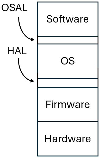 Four-tier model of the clean embedded architecture (adapted from page 267)
PART VI — Details
Chapter 30 — The Database Is a Detail
Data models hold architectural significance, whereas specific database implementations remain a mere detail. The intensity of architectural discussions stems from the inherent latency of magnetic hard drives, which demands significant engineering effort to maximize performance. Ultimately, a database functions fundamentally as a technological mechanism designed for persistent data storage.
Chapter 31 — The Web Is a Detail
Computer engineering experiences a perpetual pendulum swing between centralizing computation on servers and decentralizing it to client nodes. Graphical user interface (GUI) layouts frequently evolve due to shifting marketing requirements. The user interface must be treated as a mere detail to insulate high-level architectural components from volatile frontend changes. Architecturally, the web functions fundamentally as an input-output (I/O) device.
Chapter 32 — Frameworks Are Details
Developers often architect applications directly around a framework, which inadvertently establishes a highly tight coupling. This creates a unilateral commitment, as framework maintainers possess no reciprocal obligations or commitments toward the stability of your specific application. Solutions involve utilizing frameworks while strictly treating them as peripheral details confined to the outermost architectural layers. Through this strategic encapsulation, the objective is to leverage the framework’s benefits without absorbing its long-term architectural liabilities — conceptually equivalent to enjoying the utility without incurring the ownership overhead. In certain scenarios, structural dependencies are unavoidable, such as a Java application possessing an absolute dependency on the standard library.
Chapter 33 — Case Study: Video Sales
Architectural design begins with a comprehensive use case analysis to capture functional requirements. This initialization includes abstract use case identification to factor out common behavioral patterns, and defined use cases are systematically assigned to specific actors to establish clear operational boundaries. Following this, the structural system configuration is partitioned into distinct architectural layers, separating views, presenters, interactors, and controllers. Rigid architectural boundaries are established between components to isolate business logic from delivery mechanisms. The determination of exact physical deployment structures remains a lower-level decision that can be deliberately deferred to a later lifecycle phase.
Chapter 34 — The Missing Chapter
Runtime execution discrepancies and structural failures manifest primarily during system execution rather than design phases. Packaging by layer serves as a viable baseline architecture for simplistic applications, but it suffers from an absence of domain expressiveness, failing to overtly communicate or “shout out” the application’s underlying business use cases. Alternatively, packaging by feature concentrates all vertical slices of a functional requirement into a single, localized package. However, vertical feature organization introduces long-term maintainability challenges and boundary degradation risks in strictly enforcing architectural boundaries between distinct features.
Hexagonal architecture separation via Ports and Adapters isolates core domain logic within internal rings while relegating infrastructure concerns to external rings. These inner architectural rings encapsulate the Ubiquitous Language presented in “Book Review: ‘Domain-Driven Design kompakt’ by Vaughn Vernon”. Packaging by component may operate independently from the presented component principles such as SOLID, REP, CCP, and CRP, offering key internal encapsulation retention. Consolidating domain logic and persistence code within a single package prevents component-internal interfaces, such as an OrderRepository, from being exposed publicly. The C4 Software Architecture Model proposes a different definition of component:
“In the C4 model, a component is a grouping of related functionality encapsulated behind a well-defined interface. […] components are not separately deployable units. Instead, it’s the container that’s the deployable unit.”
Packaging by component yields a significant architectural encapsulation benefit, as vertical slicing is achieved while preserving the layered architecture as an internal implementation detail of the component. Furthermore, this sub-component architecture must still preserve the strict separation of core domain logic from persistence mechanisms as an internal implementation detail.
Macro-architectural integrity is highly sensitive to implementation-level erosion caused by micro-implementation details. Object-oriented languages, particularly Java, frequently suffer from an over-use of public access modifiers. When all classes are declared public, structural organization falls short of true encapsulation, and all architectural organization styles become functionally identical since public types remain universally accessible. Leveraging packages as genuine encapsulation boundaries requires the deliberate utilization of non-public (package-private) class access levels. Team agreements to maintain architectural boundaries through peer reviews and discipline inevitably collapse under heavy production deadline pressures. A comprehensive, structural comparison of these discrete code organization methodologies is illustrated in Figure 34.8 on page 307.
Modern language constructs offer technical mechanisms to enforce alternative decoupling modalities beyond standard package boundaries. Incorporating Java 9 module isolation (Project Jigsaw) can programmatically enforce access constraints, serving as a potential technical resolution to encapsulation leakage. Conversely, utilizing independent physical source code trees to isolate ports from adapters introduces distinct tooling and maintenance overhead. The definitive architectural advice emphasizes that optimal high-level design decisions can be rapidly neutralized by undisciplined or flawed low-level implementation strategies. Structural decoupling must be consciously evaluated and maintained at both compile-time and runtime. Architectural enforcement must remain pragmatic, balancing systemic ideals against budgetary constraints, delivery timelines, team sizes, and engineering competencies. Software systems should leverage compiler constraints and static analysis tools to programmatically validate compliance with the chosen architectural style.
PART VII — Appendix
Appendix A — Architecture Archaeology
This section features an interesting collection of Uncle Bob’s projects and experience.
Appendix B — Afterword
The book concludes with final remarks from the author.
📝 Appendix: Raw Reading Notes
PART I — Introduction
Chapter 1 — What is Design and Architecture?
- Equivalence of concepts: Software design and software architecture represent identical concepts.
- Primary Architectural objective (see page 30):
The objective of software architecture is to minimize the human resources required to build and maintain the required system.
- Maintainability case study: The case study demonstrates that developing software without prioritizing maintainability increases the total cost of ownership (TCO) and decreases developer velocity.
- Productivity through TDD: Implementing Test-driven development enhances engineering productivity, as noted on page 36.
- Flawed deployment mindsets: A common, erroneous mindset dictates launching the product to the market immediately while postponing refactoring and testing for a later phase.
- Note: The designated time for optimization never materializes.
- Rebuilding the system fails to resolve the underlying issue because market pressure persists throughout the entire rebuilding phase.
Chapter 2 — A Tale of Two Values
- Dual values of software: Software systems deliver value through two primary dimensions: behavior and structure.
- The behavior of a system fulfills the specified functional requirements.
- A robust structure supports system adaptability, including maintainability and testability.
- The term “software” itself implies a medium designed to be soft and adaptable.
- Primacy of adaptability: Adaptable systems are inherently superior to systems that merely exhibit correct behavior, as adaptable systems can be fixed and evolved, whereas the latter are strictly rigid.
- Core architectural focus: The fundamental purpose and focus of software architecture is to maximize adaptability.
PART II — Starting with the Bricks: Programming Paradigms
Chapter 3 — Paradigm Overview
- Structured Programming Paradigm: The paradigm of structured programming.
Structured programming imposes disciplined control over direct transfer of control.
- Object-Oriented Programming: Object-oriented programming concepts.
Object-oriented programming imposes disciplined control over indirect transfer of control.
- Functional Programming: Functional programming concepts.
Functional programming imposes disciplined control over variable assignment.
Chapter 4 — Structured Programming
- Structured programming paradigms: Structured programming restricts the use of unconstrained transfer-of-control statements (such as
goto) and replaces them with standardized control flows like sequence, selection (if/then/else), and iteration (do/while).- This paradigm aligns with theoretical findings demonstrating that any computable program can be constructed exclusively using sequence, selection, and iteration.
- Composability of software units: Software architectures are inherently composable, built from smaller, modular sub-units.
- Mathematically, if each sub-module could be proven to operate entirely without error, the aggregate program would itself be error-free.
- In practice, empirical software testing can only demonstrate the presence of errors, never their complete absence.
- Despite this limitation, robust and comprehensive testing of individual sub-modules yields a high statistical probability that the overall system will contain minimal defects.
- Efficacy of functional decomposition: Structured functional decomposition remains a highly effective strategy for managing system complexity.
Chapter 5 — Object-Oriented Programming
- Safety in polymorphism: Object-oriented programming provides polymorphism in a safe, stable, and highly manageable manner.
- This technical capability directly enables the implementation of the Inversion of Control (IoC) paradigm, representing a critical architectural value.
- Decoupling of dependency structures: Software architects can structure source code dependencies independently, removing the constraint to follow the runtime control flow of the program.
- For example, this mechanism allows engineering teams to build core domain logic entirely independent of database access layers, successfully separating domain business logic from technical infrastructure concerns.
Chapter 6 — Functional Programming
- Immutability in functional programming: The functional programming paradigm dictates that variables cannot be explicitly altered after initialization.
- Eliminating mutable state inherently resolves critical concurrency issues, such as race conditions and resource deadlocks.
- Architectural implications of functional programming: Adopting functional principles shifts how system state and logic are distributed across an application.
- Software architects must isolate variable manipulations and state changes into dedicated, explicit modules, designated as mutable components.
- Conversely, engineering teams should encapsulate the vast majority of domain logic and runtime complexity within stateless, immutable components.
Part III — Design Principles
- Architectural goals: Enable modification, ensure easy traceability, and facilitate the reuse of middle-layer architectural components.
- Scope of middle layer: Define the middle layer at the module level, positioned directly above the source-code level.
- Core design principles: The following five principles are recognized by the acronym SOLID (note the slight differences in the definitions here compared to Wikipedia):
- SRP: The Single-Responsibility Principle
The optimal structure for a software system is heavily influenced by the social structure of the organization utilizing it, ensuring that each software module has one — and only one — reason to change. - OCP: The Open-Closed Principle
Design software systems to facilitate easy adaptation, ensuring that behavioral modifications are achieved by adding new code rather than modifying existing code. - LSP: The Liskov Substitution Principle
Constructing software systems with interchangeable objects requires that these components must be mutually substitutable. - ISP: The Interface Segregation Principle
Avoid dependencies on unutilized modules. - DIP: The Dependency Inversion Principle
Code implementing high-level policies must not depend on code implementing low-level details; instead, details must depend on policies.
- SRP: The Single-Responsibility Principle
Chapter 7 — SRP: The Single-Responsibility Principle
- Definition:
Define a module in this context as being responsible to a single actor.
- Misconception correction: Do not assume every module must perform only a single task; this rule applies strictly to functions and methods, not to modules.
- Original definition: Maintain the original definition stating that there should be only one reason to change a module.
- Future architectural mappings: Anticipate that this concept will reappear in subsequent architectural layers as the Common-Closure Principle (CCP) in chapter 13 and the axis-of-change model.
Chapter 8 — OCP: The Open-Closed Principle
- Definition:
A software entity must be open for extension but simultaneously closed to modification.
- Architectural motivation: Recognize this principle as the fundamental motivation driving software architecture.
- Core methodology:
- Decompose the system into distinct components and establish a suitable dependency hierarchy, ensuring higher-level components are protected from changes in lower-level components.
- Note that excellent illustrative examples are provided within the book.
Chapter 9 — LSP: The Liskov Substitution Principle
- Formal Liskov Substitution Principle definition:
The objective is to achieve a substitution property where if, for each object
o1of typeS, there exists an objecto2of typeTsuch that for all programsPdefined in terms ofT, the behavior ofPremains unchanged wheno1is substituted foro2, thenSis a subtype ofT. - Historical context and scope expansion: The principle was originally developed to handle inheritance in programming languages, but it should be viewed more generally to encompass all types of interfaces and components.
- Architectural impact of violations: A single violation can have a massive impact on maintainability, as numerous exceptions must subsequently be added, maintained, and understood.
Chapter 10 — ISP: The Interface Segregation Principle
- Interface specialization: Design distinct interfaces tailored to specific architectural purposes.
- Historical origin: The concept was originally defined for statically linked programming languages.
- Component generalization: The principle successfully generalizes to all categories of software components.
- General formulation: Avoid relying on modules that provide a broader scope of functionality than required.
- Component cohesion link: This concept correlates directly with the Common-Reuse Principle detailed in Chapter 13.
Chapter 11 — DIP: The Dependency Inversion Principle
- Abstraction enforcement: Source code dependencies must strictly consist of abstractions, a constraint that is historically challenging to implement.
- Dependency isolation: It remains entirely feasible to isolate concrete dependencies by utilizing factory components.
- Platform exemptions: Operating system components and core platform entities, such as the Java
Stringclass, are typically exempted from this architectural rule. - Stable abstraction constraints: Architectural stability requires adhering to strict rules regarding concrete implementation structures.
- Do not reference concrete classes.
- Do not inherit from concrete classes.
- Do not override concrete methods.
- Do not explicitly reference concrete elements by name under any circumstances.
- Abstract Factory integration: Implement the abstract factory pattern to manage dependency creation cleanly.
- A definitive illustrative diagram of this pattern is available on page 110.
- Framework mechanisms, such as the Spring (Boot) application context, fully automate this specific instantiation workflow.
PART IV — Component Principles
Chapter 12 — Components
- Definition:
Components represent the smallest deployable units within an architecture, exemplified by formats such as JAR files.
- Deployment evolution: A historical review of compilers and linkers demonstrates that modern plug-in architectures—utilizing artifacts like JARs and DLLs—have become the industry standard.
Chapter 13 — Component Cohesion
- REP: Reuse-Release-Equivalence Principle
- Definition:
The granularity of reuse is the granularity of the release.
- You can only reuse what is in one named component with the same version number, release documentation, etc.
- Definition:
- CCP: Common-Closure Principle
- Definition:
Group classes that are modified for the same reasons and at the same time into the same components. Conversely, separate classes that are modified for different reasons and at different times into different components.
- There should only be one reason to change a module.
- This is a generalization of the Single-Responsibility Principle (SRP).
- It is also related to the Open-Closed Principle (OCP): “Closed for modifications” cannot be reached completely. CCP requires this on a “higher component level.”
- Generalization of SRP and OCP: Group all elements that are modified for the same reasons and at the same time. Conversely, separate all elements that are modified for different reasons and at different times.
- Definition:
- CRP: Common-Reuse Principle
- Definition:
Do not force the users of a component to depend on elements that they do not require.
- Put components together that are usually used together.
- Separate classes that are usually not used together.
- It relates to the Interface Segregation Principle (ISP): ISP requires separating interfaces when methods are usually not used together.
- Common denominator of ISP and CRP: Do not create dependencies on elements that you do not require.
- Definition:
- The Tension Triad of Component Principles
Tension Triad of Component Principles (adapted from page 126)
- The three principles are in opposition.
- REP tends to create big components to reduce their number.
- CRP tends to create small components to reduce unnecessary dependencies.
- CCP organizes the components from a maintenance effort point of view.
- The optimal component definition may change over time and project affordances. A tension diagram is on page 126.
Chapter 14 — Component Coupling
- ADP: Acyclic-Dependencies Principle
- Definition:
Allow no cycles in the component dependency graph.
- Violations result in complex integration management and impact analyses.
- Overcome cycles by applying the Dependency Inversion Principle (DIP) or by creating a new component.
- Definition:
- Top-Down Design Pitfalls
- Top-down design is not recommended because there is not enough knowledge upfront.
- Component design is controlled by the Single-Responsibility Principle (SRP) and the Common-Closure Principle (CCP).
- SDP: Stable-Dependencies Principle
- Definition:
Dependencies should run in the direction of stability.
- Stability of components is defined as the effort required to change the component.
- Metrics for instability (
I):Fan-in: number of incoming dependencies.Fan-out: number of outgoing dependencies.I = Fan-out / (Fan-out + Fan-in)I = 0is maximally stable,I = 1is maximally unstable.
- SDP states that the
I-value of a component should be higher than theI-values of the components it depends upon. - Note: Not all components should be stable.
- Definition:
- SAP: Stable-Abstractions Principle
- Definition:
A component should be as abstract as it is stable.
- Common components should be stable but also accessible by many components; therefore, they should be abstract.
- SAP states that the stability of a component should relate to its abstraction.
- SAP and SDP combined represent a component-level equivalent of the Dependency Inversion Principle (DIP).
- Metrics for abstraction (
A) of components:N_c: Number of classes in a component.N_a: Number of abstract classes and interfaces in a component.A: Degree of abstraction.A = N_a / N_cA = 0means no abstract classes,A = 1means all classes are abstract.
- Definition:
- The
I/AGraph and Zones of Exclusion
Zones of Exclusion depict on page 145 (image copied from Breaking Down ‘Clean Architecture’ by Uncle Bob — Part III by Divya Saravanan)
- The
I/Agraph with zones of exclusion on page 145 depicts the following relationships: - Zone of Pain: Highly stable (many dependent components) and highly concrete (hard to change). Examples include database schemas and the Java
Stringclass. - Zone of Uselessness: Highly abstract classes that are not referenced by any other components.
- Main Sequence: Represents the optimal balance between stability and abstraction.
- Distance
Dfrom the Main Sequence:D = |A + I - 1| - This metric enables statistical analysis, such as:
- Examining the normal distribution and analyzing components where
Dis greater than the standard deviation. - Monitoring the value of
Dfor a specific component over time.
- Examining the normal distribution and analyzing components where
- The
Part V — Architecture
Chapter 15 — What is Architecture?
- System Structure: Provide a “form” or structure for software systems.
- Components and their interactions form this structure.
- Behavior Determination: Note that system behavior is determined by functional requirements.
- Supporting the required use cases is the primary objective.
- Cost Minimization: Goal is to minimize lifetime costs across multiple phases.
- Development
- Deployment
- Operations
- Maintenance
- Option Management: Create and maintain architectural options.
A good software architect maximizes the number of decisions not yet made.
- Separate policies (business logic) from details.
- Examples of details include databases, web frameworks, and device specifics.
Chapter 16 — Independence
- Operations Planning: Defer decisions regarding operations as long as possible.
- If the component structure is robust, concrete deployment and operational modes can be determined at a later stage.
- Team Structure Alignment: Consider team organization within component design by accounting for Conway’s law.
[O]rganizations which design systems (in the broad sense used here) are constrained to produce designs which are copies of the communication structures of these organizations.
- Decoupling: Implement architectural decoupling across multiple dimensions.
- Decouple horizontal layers.
- Adhere to the Single-Responsibility Principle (SRP) and the Common-Closure Principle (CCP).
- Decouple implementation details (e.g., UI and database access) from core business rules.
- Decouple vertical use cases.
- For example, “Creating an order” is distinct from “Deleting an order.”
- This separation enables independent development and deployment.
- Decouple horizontal layers.
- Duplication Classification: Differentiate between real duplication and accidental duplication.
- Eliminate real duplication systematically.
- Resist the urge to eliminate accidental duplication.
- For example, similar-looking display outputs have a high probability of diverging in the future if they do not represent the same core concept.
- Decoupling (again): Evaluate decoupling across different architectural levels.
- Decoupling can occur at the source code, deployment, or service level.
- Defer the selection of the specific level as long as possible.
- Note that the most suitable decoupling level for a system may change over time.
Chapter 17 — Boundaries: Drawing Lines
- Boundary Separation: Draw lines to protect important components, such as business rules and policies, from implementation details.
- Plugin Architecture: Imagine these boundary lines as a plugin system.
- You can plug in different GUIs or databases to your system as long as the business cases remain protected against these volatile details.
- Architectural Principles: Boundary lines represent a concrete application of the Dependency Inversion Principle (DIP) and the Stable Abstractions Principle (SAP).
Chapter 18 — Boundary Anatomy
- Deployment Monoliths: Contrast monolithic architectures with multi-deployment unit configurations regarding package boundaries.
- These represent different methodology variations used to enforce component paradigms.
- Modulith: A single deployment unit contains all logical components, meaning component paradigms remain highly valuable for isolation, testing, and structural simplicity.
- Deployments: Each individual component is built and isolated as a separate deployment unit.
- Runtime Execution Boundaries: Define execution boundaries operating within a single physical runtime environment.
- Threads:
- Distinct runtime execution paths operating within the exact same process space.
- Thread communication features highly efficient data exchange via shared memory access.
- Local Processes:
- Multiple component instances run on the same physical machine but inside isolated operating system processes.
- Process communication relies on slower mechanisms via standard inter-process communication (IPC).
- Each individual process can internally spawn and employ multiple threads if required.
- Threads:
- Service Boundaries: Establish architectural boundaries across distributed services.
- Multiple components or instances are instantiated as independent services.
- Service communication occurs via standard network protocols, which introduces latency and is relatively slow.
- Each individual service can internally utilize local processes or threads if desired.
- Services offer the flexibility to be deployed across completely different physical or virtual machines.
Chapter 19 — Policies and Level
- Business Logic Classification: Policies represent high-level business logic within the application core.
- Architectural Level Definition: Define the precise metric for an architectural “level” within a system.
- Strict definition of level:
A level is defined by the distance from the system inputs and outputs.
- Components sharing the exact same relative distance from inputs or outputs should be grouped together on the same architectural level.
- Note: The architectural case study spanning pages 196–198 explicitly applies the Single-Responsibility Principle (SRP), Open-Closed Principle (OCP), Common-Closure Principle (CCP), Dependency Inversion Principle (DIP), Stable-Dependencies Principle (SDP), and Stable-Abstractions Principle (SAP).
- Strict definition of level:
Chapter 20 — Business Rules
- Critical Business Rules: These represent policies or procedures that directly result in earning or saving business capital.
- They would also be applied even if no computer systems were used.
- Critical Business Data: This refers to the data required to calculate or execute the critical business rules.
- Entity: An object within a computer system that represents a small portion of the critical business rules.
- Developers should create a dedicated class for this and separate it completely from all other aspects of the system.
- Application Use Cases: These rules are not as puristic as critical business rules and represent application-specific business rules instead.
- They are required to be handled specifically within an automated system.
- For example, the contact data of a customer must be created before a user can place an order.
- Use cases orchestrate entities, but entities are not aware of the use cases. Use cases operate closer to the input and output mechanisms but remain strictly protected from system details.
- Request and Response Models: These models are required so that use cases can receive input and produce output.
- However, these classes must remain entirely free of dependencies on frameworks or even on the entities themselves.
- They will change over time for different reasons, and coupling them would violate both the Common-Closure Principle (CCP) and the Single-Responsibility Principle (SRP).
Chapter 21 — Screaming Architecture
- Screaming Architecture: An application’s architecture should clearly broadcast its underlying purpose. Because application use cases are first-class citizens and represent the primary objective of the system, the architecture must prominently emphasize these use cases rather than the frameworks being utilized.
- Frameworks as Details: Software frameworks are merely technical tools rather than an overriding philosophy or way of life. They should be treated strictly as low-level implementation details.
- Decoupled Unit Testing: When use cases are kept completely free of framework dependencies, developers can easily apply lightweight unit tests to verify both application use cases and business entities in isolation.
Chapter 22 — The Clean Architecture
- Architectures influencing Clean Architecture
- Three important influencing architectures:
- Hexagonal architecture (later frequently referred to as Ports and Adapters)
- DCI - Data, Context and Interaction
- BCE - Boundary Control Entity
- Common Architectural Characteristics: These structural designs share fundamental operational principles.
- Usage of layers to separate distinct system aspects: At least one level for business rules and an additional level for user and system interfaces.
- Comprehensive framework independence.
- High testability.
- Complete UI independence.
- Complete database independence.
- Independence from external agencies.
- Three important influencing architectures:
- Clean Architecture overview: The schematic diagram illustrates the concentric layout of the architecture.
Architecture overview schematic diagram depict on page 212 (image copied from The Clean Architecture)
- Dependency Rule: This central rule governs the direction of all source code dependencies.
- Definition:
Source code dependencies must only point inward, toward higher-level policies.
- Entities encapsulate enterprise-wide business rules, representing critical business logic.
- The probability of structural change is low.
- Use cases realize application-specific business rules.
- Structural modifications here do not affect entities, meaning changes in the GUI or database have no impact on the core logic.
- Definition:
- Interface Adapters: This layer translates data between the format convenient for use cases and entities, and the format convenient for external components.
- Goal: Adapt interfaces between entities and use cases on one side and external mechanisms like databases or web UIs on the other.
- Maintain absolute independence from specific frameworks or concrete technologies.
- Frameworks and Drivers: This outermost layer contains concrete technological details and external tools.
- Contains all technological implementations and configuration details.
- Demonstrates the highest structural distance from the core business logic.
- Layer Scalability: The system permits structural modifications to the number of architectural circles.
- Engineers can introduce additional layers if required, provided the dependency rule strictly holds.
- Boundary Crossing: Architectural boundaries are crossed by consistently applying the Dependency Inversion Principle (DIP).
- Employ simple Data Transfer Objects (DTOs) to cross layer boundaries. Do not utilize entities or framework-specific types for communication.
- Application Flow Reference: Page 217 includes a concrete example demonstrating standard cross-boundary data flows.
Chapter 23 — Presenters and Humble Objects
- The Humble Object Pattern: Originally defined to separate hard-to-test system behavior from behavior that is simple to test.
- The Humble Object contains hard-to-test behavior in a highly reduced manner.
- User interface (UI) interactions are a primary example of behavior that is often difficult to test.
- Presenters and Views: Architectural components designed to isolate user interface dependencies.
- The View component acts as the Humble Object, moving data directly to the Graphical User Interface (GUI) without modifying it.
- The Presenter component is responsible for formatting data into the required structures and populating the View Model.
- The View Model stores all presentation-relevant data and attributes, allowing the View to access them safely.
- Database Gateways: Interfaces decoupled from the underlying database implementation to enable ease of testing.
- Each required data access operation at the use-case level is defined as an interface.
- Database gateways implement these use-case interfaces within the database layer.
- While the gateway implementation itself is not a Humble Object, the use-case interfaces can be tested easily.
- Data Mappers, such as Object-Relational Mapping (ORM) frameworks, are strictly classified as database components.
- Service Listeners: System components that handle external service communications.
- Service listeners are implemented analogously to database gateways.
Chapter 24 — Partial Boundaries
- Partial Architectural Boundaries: An alternative approach when establishing complete architectural boundaries proves cost-prohibitive.
- Option 1: Omission of layer-specific builds: Eliminates independent packaging to reduce the administrative overhead of release and deployment management.
- Despite reduced operational overhead, the core development and maintenance efforts remain unchanged.
- Option 2: The Strategy Pattern: Implements a dynamic behavioral switch to establish boundaries.
- Architectural risk: The core dependency rules can be bypassed or violated with relative simplicity.
- Option 3: The Facade Pattern: Utilizes a unified structural interface to hide underlying component complexity.
- Architectural risk: Transitive dependencies persist across the boundary.
- This approach enforces an even less rigorous boundary than the Strategy Pattern.
- Option 1: Omission of layer-specific builds: Eliminates independent packaging to reduce the administrative overhead of release and deployment management.
Chapter 25 — Layers and Boundaries
- Strategic Placement of Full Architectural Boundaries: The economic and structural decisions governing where full boundaries should be implemented.
- Implementing full architectural boundaries introduces significant up-front costs and ongoing maintenance overhead.
- Conversely, omitting necessary boundaries can impose even greater long-term maintenance and technical debt costs.
- The Wumpus World Case Study: An insightful example included within this chapter on pages 228–233 to illustrate these architectural boundary concepts.
Chapter 26 — The Main Component
- The Main Component as the Ultimate Detail: The low-level entry point responsible for system configuration and bootstrapping.
- It handles the creation of all factories, strategic implementations, and global instances.
- All system dependencies should be injected by the dependency injection framework at hand and distributed throughout the entire system.
- It is inherently classified as a non-clean component operating within the outermost ring of the Clean Architecture model.
Chapter 27 — Services: Great and Small
- The Fallacy of Service-Oriented Architecture: Clarifying the distinction between runtime topology and true system architecture.
- The usage of services represents a deployment and runtime detail rather than an intrinsic architectural characteristic.
- True architecture is defined by boundaries that separate high-level policies from low-level details.
- The Decoupling Trap: Services appear decoupled at runtime, but this is often a misconception.
- When a data object transferred between services changes, domain coupling emerges, reflecting a dependency similar to function calls within a single program.
- The Independent Development and Deployment Trap: The belief that services grant total operational autonomy.
- In practice, deployment activities across services must still be meticulously coordinated.
- Cross-Cutting Concerns in Service Architectures: Managing system-wide requirements that span multiple service boundaries.
- Cross-cutting concerns are not handled more easily by microservice architectures than by other structural models, as illustrated by the “Cat Problem” case study on pages 243–246.
- These concerns can be resolved effectively only if each service is built upon SOLID component design principles.
- This structural requirement is absolute because the runtime environment remains merely an architectural detail.
- The underlying reason is straightforward: the cross-cutting concern does not exist between distinct services, but rather cuts directly across them.
Chapter 28 — The Test Boundary
- System Integration: Tests are a fundamental part of the system rather than an external or peripheral entity.
- The Fragile Test Problem: Changes made to central components can inadvertently result in a massive number of test failures.
- Volatility Mitigation: Tests must not depend on volatile components, such as Graphical User Interfaces (GUIs).
- Decoupled Test APIs: Developers should provide a dedicated test Application Programming Interface (API) that remains completely independent of the application structure.
- Structural Separation: It is critical to ensure the strict structural decoupling of tests from the production codebase.
- Security and Isolation Aspects: Tests should be packaged into independent deployments to guarantee that no dependencies flow from production code to test code.
Chapter 29 — Clean Embedded Architecture
- Firmware definition: Firmware represents software that is tightly coupled to a specific technology.
- Utilizing SQL constitutes firmware.
- Interfacing with the Android API constitutes firmware.
- Architectural paradigm: Cease the development of firmware-centric code and transition to writing pure software.
- Embedded systems solution: The optimal architecture for embedded systems relies on a three-tier model.
- The model comprises three distinct layers: Software, Firmware, and Hardware.
- Implement a Hardware Abstraction Layer (HAL) between the software and firmware tiers.
- This is an established industry concept that predates Windows on personal computers.
- The HAL must encapsulate all low-level hardware specificities.
- The processor serves as a low-level detail, meaning the firmware layer must isolate the rest of the system from processor-specific architecture.
- Operating system encapsulation: The operating system must be treated as a low-level implementation detail.
- You can add an additional layer OS: Software, OS, Firmware, and Hardware.
- Integrate the operating system alongside an Operating System Abstraction Layer (OSAL) between software and firmware.
Four-tier model of the clean embedded architecture (adapted from page 267)
PART VI — Details
Chapter 30 — The Database Is a Detail
- Data modeling priority: Data models hold architectural significance, whereas specific database implementations remain a mere detail.
- Drivers of intense debate: The intensity of architectural discussions stems from the inherent latency of magnetic hard drives, which demands significant engineering effort to maximize performance. Ultimately, a database functions fundamentally as a technological mechanism designed for persistent data storage.
Chapter 31 — The Web Is a Detail
- Architectural oscillation: Computer engineering experiences a perpetual pendulum swing between centralizing computation on servers and decentralizing it to client nodes.
- UI decoupling strategies: Graphical user interface (GUI) layouts frequently evolve due to shifting marketing requirements.
- The user interface must be treated as a mere detail to insulate high-level architectural components from volatile frontend changes.
- Architecturally, the web functions fundamentally as an input-output (I/O) device.
Chapter 32 — Frameworks Are Details
- Asymmetric frameworks relationship:
- Developers often architect applications directly around a framework, which inadvertently establishes a highly tight coupling.
- Unilateral commitment: Framework maintainers possess no reciprocal obligations or commitments toward the stability of your specific application.
- Decoupling strategies: Solutions involve utilizing frameworks while strictly treating them as peripheral details confined to the outermost architectural layers.
- Strategic encapsulation: The objective is to leverage the framework’s benefits without absorbing its long-term architectural liabilities—conceptually equivalent to enjoying the utility without incurring the ownership overhead.
- Inherent platform dependencies: In certain scenarios, structural dependencies are unavoidable, such as a Java application possessing an absolute dependency on the standard library.
Chapter 33 — Case Study: Video Sales
- Use case analysis initialization: Architectural design begins with a comprehensive use case analysis to capture functional requirements.
- Abstract use case identification: The analysis encompasses abstract use cases that factor out common behavioral patterns.
- Actor allocation: Defined use cases are systematically assigned to specific actors to establish clear operational boundaries.
- Component architecture decomposition: The structural system configuration is partitioned into distinct architectural layers, separating views, presenters, interactors, and controllers.
- Boundary enforcement: Rigid architectural boundaries are established between components to isolate business logic from delivery mechanisms.
- Deferred deployment configuration: The determination of exact physical deployment structures remains a lower-level decision that can be deliberately deferred to a later lifecycle phase.
Chapter 34 — The Missing Chapter
- Runtime execution vulnerability: Architectural discrepancies and structural failures manifest primarily during system execution rather than design phases.
- Horizontal layering limitations: Packaging by layer serves as a viable baseline architecture for simplistic applications.
- Absence of domain expressiveness: Horizontal layering fails to overtly communicate or “shout out” the application’s underlying business use cases.
- Vertical feature slicing: Packaging by feature concentrates all vertical slices of a functional requirement into a single, localized package.
- Boundary degradation risks: Vertical feature organization introduces long-term maintainability challenges in strictly enforcing architectural boundaries between distinct features.
- Hexagonal architectural separation: Ports and Adapters isolates core domain logic within internal rings while relegating infrastructure concerns to external rings.
- Domain-Driven Design integration: Inner architectural rings encapsulate the Ubiquitous Language presented in “Book Review: ‘Domain-Driven Design kompakt’ by Vaughn Vernon”.
- Component-Centric Organization: Packaging by component may operate independently from the presented component principles such as SOLID, REP, CCP, and CRP:
- Internal encapsulation retention: Consolidating domain logic and persistence code within a single package prevents component-internal interfaces, such as an
OrderRepository, from being exposed publicly. - C4 model component: The C4 Software Architecture Model proposes a different definition of component:
“In the C4 model, a component is a grouping of related functionality encapsulated behind a well-defined interface. […] components are not separately deployable units. Instead, it’s the container that’s the deployable unit.”
- Architectural encapsulation benefit: Vertical slicing is achieved while preserving the layered architecture as an internal implementation detail of the component.
- Persistence abstraction maintenance: Sub-component architecture must still preserve the strict separation of core domain logic from persistence mechanisms as an internal implementation detail.
- Internal encapsulation retention: Consolidating domain logic and persistence code within a single package prevents component-internal interfaces, such as an
- Implementation-level erosion: The integrity of macro-architectural designs is highly sensitive to micro-implementation details.
- Overuse of public access modifiers: Object-oriented languages, particularly Java, frequently suffer from an over-allocation of the
publicaccess modifier. - Structural organization versus true encapsulation:
- When all classes are declared public, all architectural organization styles become functionally identical since public types remain universally accessible.
- Leveraging packages as genuine encapsulation boundaries requires the deliberate utilization of non-public (package-private) class access levels.
- Team agreements to maintain architectural boundaries through peer reviews and discipline inevitably collapse under heavy production deadline pressures.
- Overuse of public access modifiers: Object-oriented languages, particularly Java, frequently suffer from an over-allocation of the
- Structural comparison matrices: A comprehensive, structural comparison of these discrete code organization methodologies is illustrated in figure 34.8 on page 307.
- Alternative decoupling modalities: Modern language constructs offer technical mechanisms to enforce structural boundaries beyond standard package boundaries.
- Java 9 module isolation: Incorporating the Java 9 Module System (Project Jigsaw) can programmatically enforce access constraints, serving as a potential technical resolution to encapsulation leakage.
- Source tree segregation: Utilizing independent physical source code trees to isolate ports from adapters introduces distinct tooling and maintenance overhead.
- The definitive architectural advice:
- Implementation strategy dominance: Optimal high-level design decisions can be rapidly neutralized by undisciplined or flawed low-level implementation strategies.
- Multidimensional decoupling: Structural decoupling must be consciously evaluated and maintained at both compile-time and runtime.
- Pragmatic boundary optimization: Architectural enforcement must remain pragmatic, balancing systemic ideals against budgetary constraints, delivery timelines, team sizes, and engineering competencies.
- Compiler-driven compliance: Software systems should leverage compiler constraints and static analysis tools to programmatically validate compliance with the chosen architectural style.
PART VII — Appendix
Appendix A — Architecture Archaeology
- Interesting collection of Uncle Bob’s projects and experience.
Thoughts on this post?
Feel free to send me an email with your comments or questions.
Feedback via Email